A MIDI Player on Eight Floppy Drives
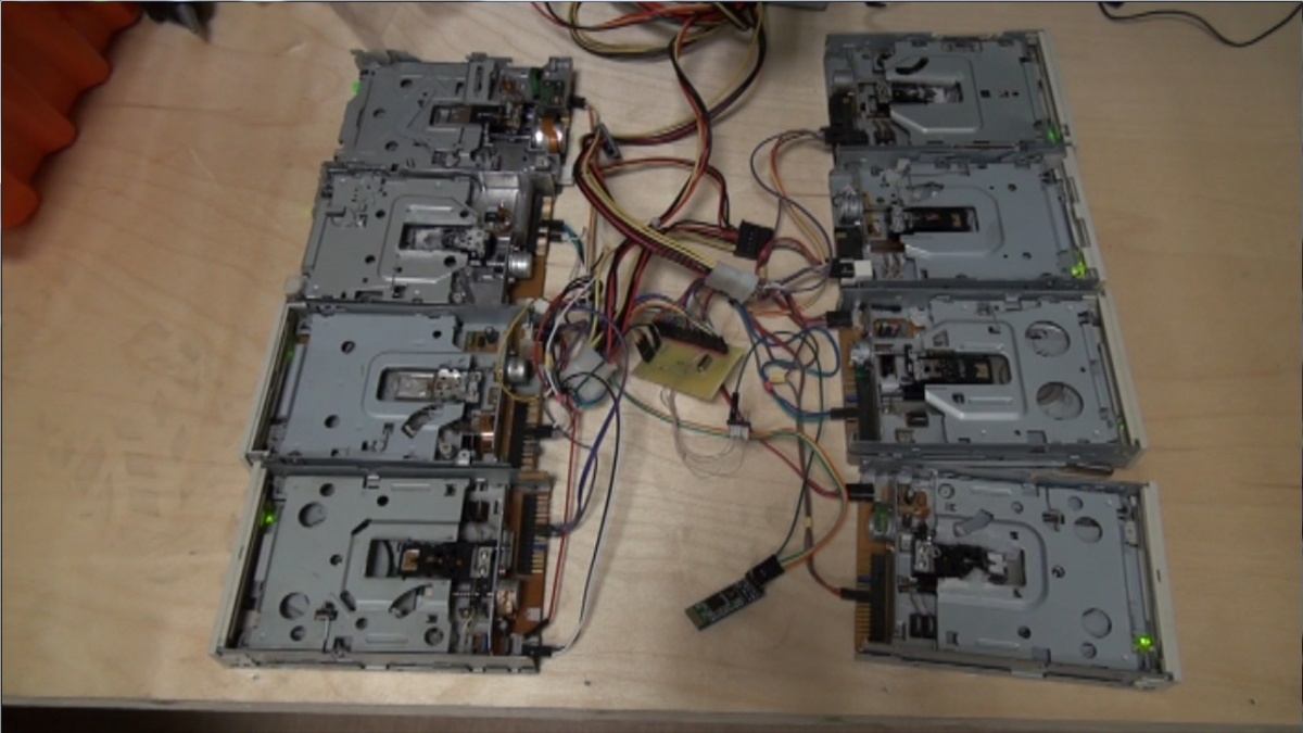
DIYSome times ago, I watched a video about singing floppy drives and a heap of written off computers, and decided to make something of the kind.

Make it on Arduino like the rest? Seriously? As they say, f*ck the system! I decided to make it on Atmega8A, as that’s what I had at hand. I also decided that wires were unnecessary, and found HC-05.
Let’s go!
The Circuit
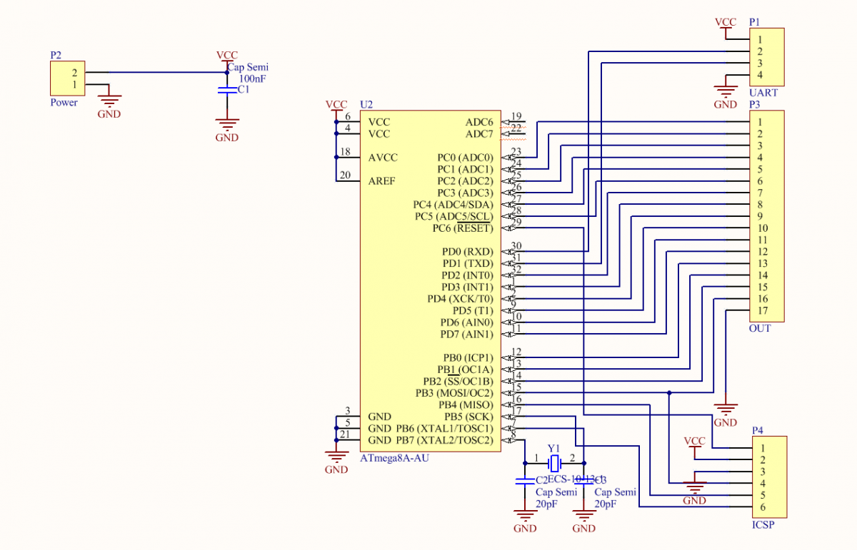
As usual, the first stage is the circuit. No problem with that.

It is simple, without unnecessary bells and whistles.
The Board
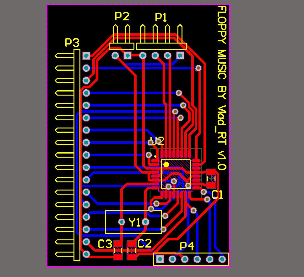
It was no problem to make it with the help of the photoresist. Scattered everything in 1o minutes and produced it in an hour.


The Code
Now, the fun part begins — programming. To save some time, I decided to write in C. But I made the same mistake at the very beginning.
It was about controlling floppy drives. As you know, if Direct pin = 0, and we give impulses to Step, a floppy drive steps forward, and if Direct pin = 1, it makes a step back. But a floppy drive has only 80 steps. What can we do about that? The solution is simple. A floppy drive can make half a step if we change the state of Step, rather than pulsing it. It’s better to do it this way:
Step ^= (1<
void output(int drive) { // drive – the Floppy drive number 1 - 8
    int position = drive - 1;
            if(currentPosition[position] >= max)direct |= 1 << position;
            if(currentPosition[position] <= 0)direct &= ~(1<
Done! Now, let’s deal with timers. Set the timer to the CTC mode with the division by 8 and allow interrupt by Output Compare (hereinafter OC). Put 40 in the OCR. An OC event occurs approximately in 40 µs. The interrupt handler is quite large.
void Action(){
        if(fr1 != 0){
        currentTick[0]++;
            if(currentTick[0] >= fr1){ //fr* - periods of channels in µs
            output(1);
            currentTick[0]=0;
            }
        };
        if(fr2 != 0){
        currentTick[1]++;
            if(currentTick[1] >= fr2){
            currentTick[1]=0;
            output(2);
            }
        };
        if(fr3 != 0){
        currentTick[2]++;
            if(currentTick[2] >= fr3){
                output(3);
                currentTick[2]=0;
            }
        };
        if(fr4 != 0){
        currentTick[3]++;
            if(currentTick[3] >= fr4){
                currentTick[3]=0;
                output(4);
            }
        };
        if(fr5 != 0){
        currentTick[4]++;
            if(currentTick[4] >= fr5){
            currentTick[4]=0;
                output(5);
            }
        };
        if(fr6 != 0){
        currentTick[5]++;
            if(currentTick[5] >= fr6){
            currentTick[5]=0;
            output(6);
            }
        };
        if(fr7 != 0){
        currentTick[6]++;
            if(currentTick[6] >= fr7){
                currentTick[6]=0;
                output(7);
            }
        };
        if(fr8 != 0){
        currentTick[7]++;
            if(currentTick[7] >= fr8){
                currentTick[7]=0;
                output(8);
            }
        };
}
ISR(TIMER2_COMP_vect){
Action();
}
Now, the connection with the computer. Here we proceed as follows. Pass a string with a macro in the header (C/F) -> the body (number) -> the end of the package (‘;’). First, processing by the state machine:
void parse(){
char data = UDR;
    switch(data){
        case 'C': tmp_int = 0; SM= data; break;   // С – it’s the channel macro
        case 'F': tmp_int = 0; SM= data; break;   // F - frequencies
        case '0':
        case '1':
        case '2':
        case '3':
        case '4':
        case '5':
        case '6':
        case '7':
        case '8':
        case '9': tmp_int = tmp_int * 10 + (data -'0'); break;
        case ';': switch(SM){
                        case 'C': channel=tmp_int; break;
                        case 'F': freq = tmp_int; break;
                    }; play(freq, channel); break;  //in play, we recount the period, taking into account the clock frequency, then write it to fr*
                    case 'R' : resetAll(); break;
        default: break;
    }
}
Second, we accept only in the Idle state:
while ( UCSRA & (1<
— No! How do we control it?
I didn’t feel like writing the control program from scratch, so I added functionality to HETC control terminal. Its interface is quite simple, so I’m not going to write much. The only thing is to select the Floppy drive and the COM-port of the device, then Connect.
Yes, you can do it without the Bluetooth, it’s just the way I see it.
Select the Midi file and….
Source Code
Ropes — Fast Strings

Comments