DIY. An Astro Tracker in Two Nights
DIYAfter reading an article about amateur astronomy, I decided to take pictures of stars with the help of a common camera using no telescope. In the mentioned article I learnt about Astro Trackers. An Astro Tracker is a device that is used to compensate rotation of the sky of stars in long-exposures.
Googling for a while, I found out that it’s no problem to buy them, but the price was a bit high. For example, the cheapest Vixin Ploarie Star Tracker costs $400 plus delivery charges. Its carrying capacity also raised doubts. Instead of the wide-angle lens, I was planning to use 70-200⁄2.8. Together with the camera they weigh around a 3-3.5 pounds.
When I was looking for the necessary information, it turned out that people make the so-called Barn Door Trackers, for example: this one, that and other. The operating principle is simple. It consists of two pieces of plywood joined by a door hinge. One of them turns with the same speed as the Earth revolves round its axis. The door hinge axis is directed at the Pole Star. The bottom piece of wood mates on an ordinary camera tripod. As for the movable part, camera attaches to the top piece via a photographic ball head (you can buy it at any camera store).
So, I was eager to make such a tracker by myself, as without it I could only take pictures as the following one:

I had all the necessary things. I decided to use this tracker as a basis. There you will also find description of calculation methods for all the basic parameters.
I decided to go with a 0.04 inches plywood as I had the experience of laser cutting it in my workshop. Plus, this material is really cheap and handy. As for reliability, I was not sure at the time. I could tell about it after the operation testing.
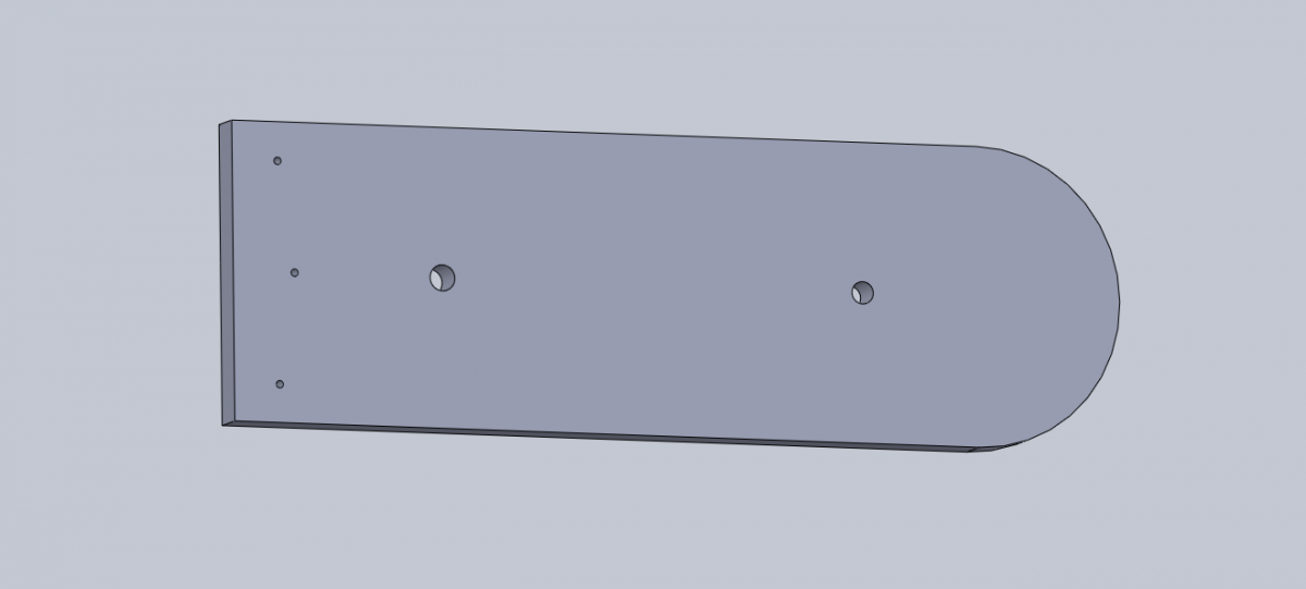
First of all, I designed the necessary model in CAD. I had to calculate the radius and the rotation speed of the pin. The radius was 7.2 inches in for М5 bolt with 0.03 inches thread pitch and the nut rotation speed of 1 rpm. I chose M5 bolt as a compromise between reliability and the thread pitch.

Since I was going to take shots with 70-200⁄2.8, I had to calculate the number of engine steps per minute so that there would be no blurs within one pixel. After all calculations, I made a tenfold spare so that manufacturing errors would not worsen the situation cardinally.
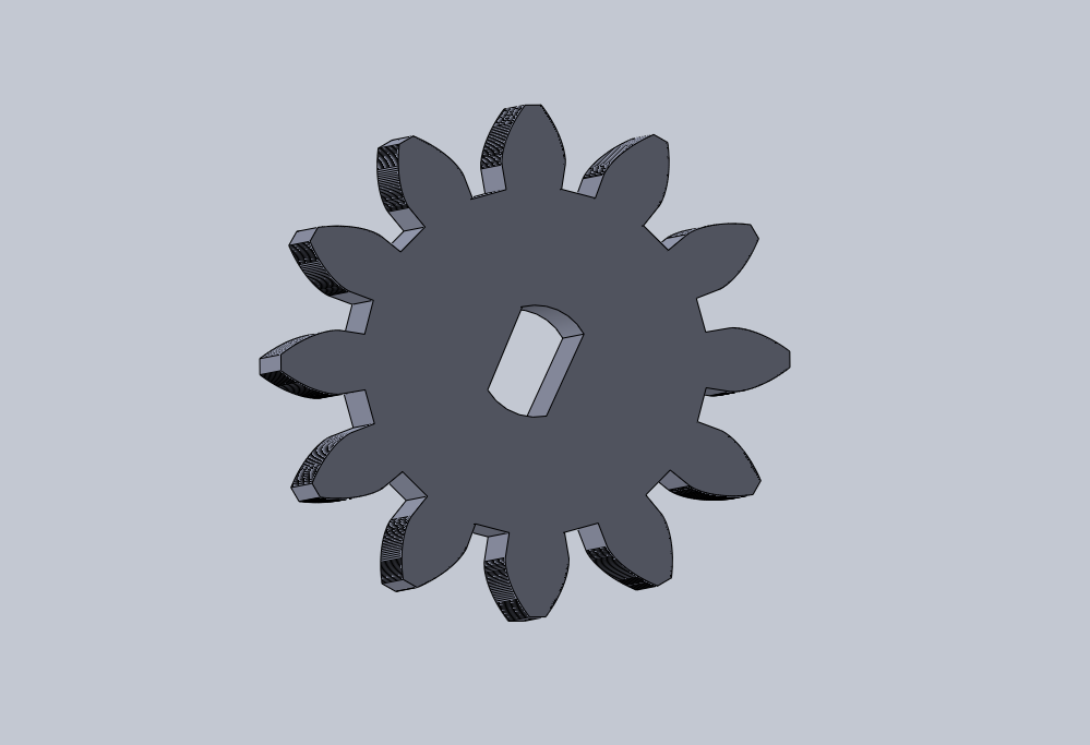
As for gears that were used in the original design, I decided to cut them from plywood or acryl with a laser.
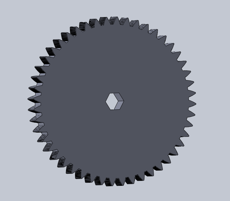
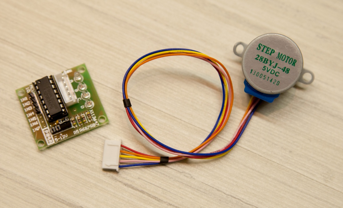
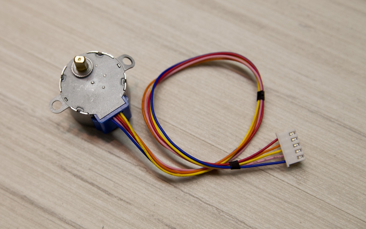
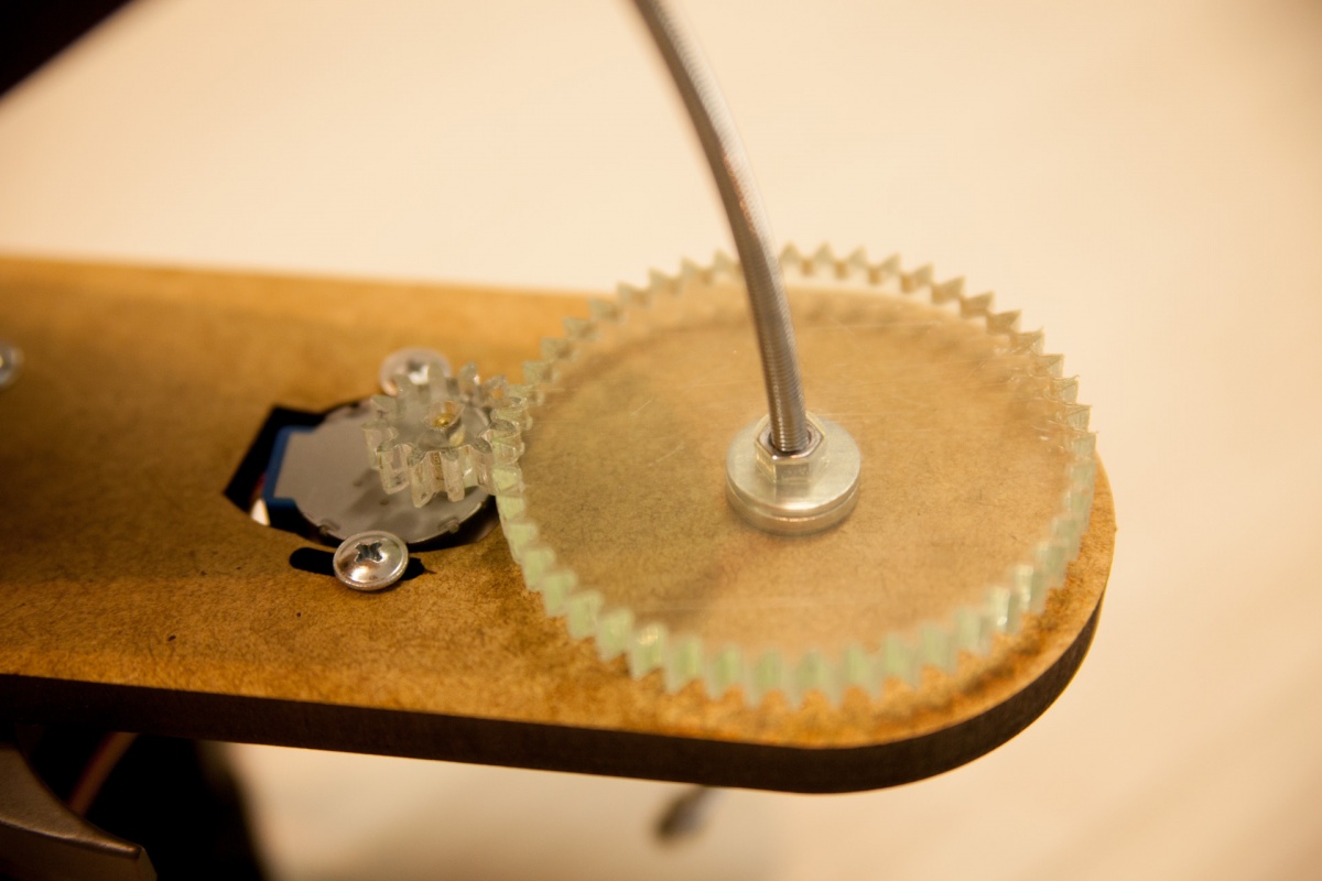
I used 28BYJ-48 stepper motor, which I had before. It had been gathering dust for a while, so it was high time to use it. The motor costs less than $2 on eBay including delivery. It’s fed by 5-12 V. It makes one shaft rotation in 64 steps. It also has a reducer with coefficient of about 63.68395:1. Thus, the external axis performs one rotation in 2037 steps in a four-step mode or 4075 steps in an eight-step mode. The rotational power is not big, but it’s more than enough for the current task. Some people managed to make it perform 15 rpm but with the help of increasing the power supply up to 12 V. I decided that 4 rpm would be enough for me and made gears of four-to-one ratio so that the nut on the bolt would make one rotation in four motor rotations.
I bought a door hinge with a minimal backlash and used its size to define the width of the pieces of plywood. I bought a bolt at the same store. Then I bought some mounting materials and ordered a small ball head on eBay. Since I have not received it yet, I used one from the old tripod.
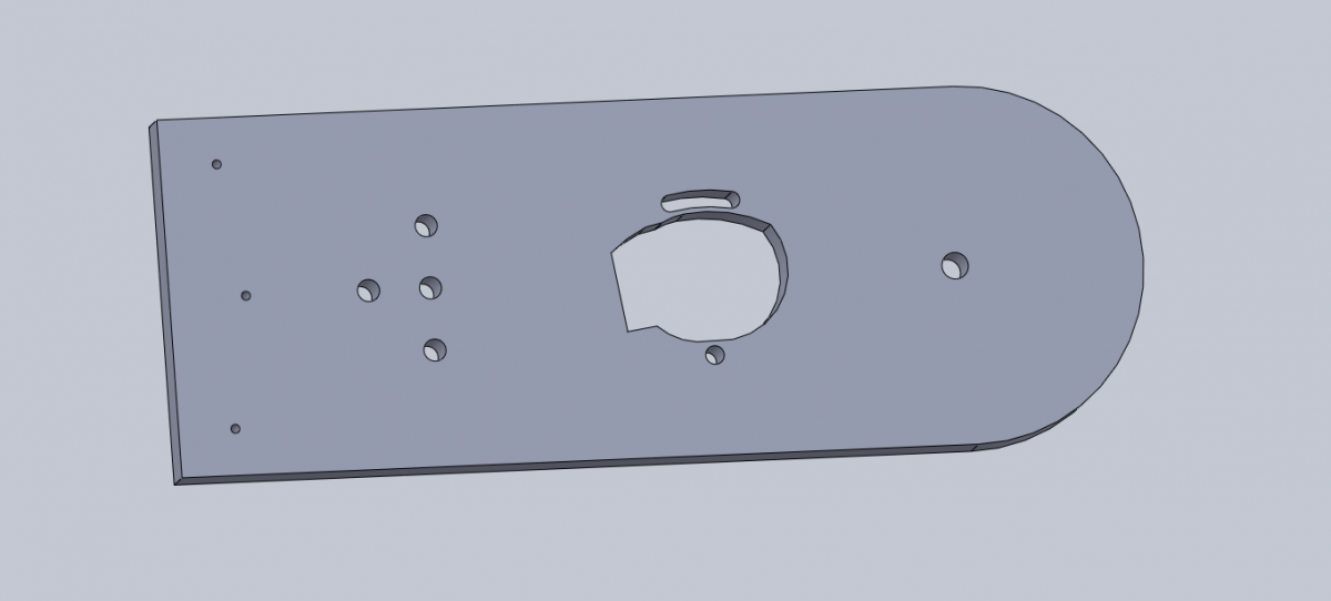
I drilled holes for mounting to the removable Manfrotto 804RC2 photohead board. I also made holes for the motor and covered the distance adjustment between the gears by means of the motor rotations round one of the mounting holes.
When I was finally satisfied with the draft, I brought it to be cut and came back with these great components.

The gears were cut from acryl and plywood. It did not turn out well with acryl, as teeth ends melted. So I had to cure them with a file. To my mind, the stroke of plywood is smoother. But we’ll see.
The gear fastening to the nut is really simple. It’s a hole in the form of a hexahedron with minimum tolerance. Acryl is of 0.3 inches caliber, so I could place two M5 nuts.

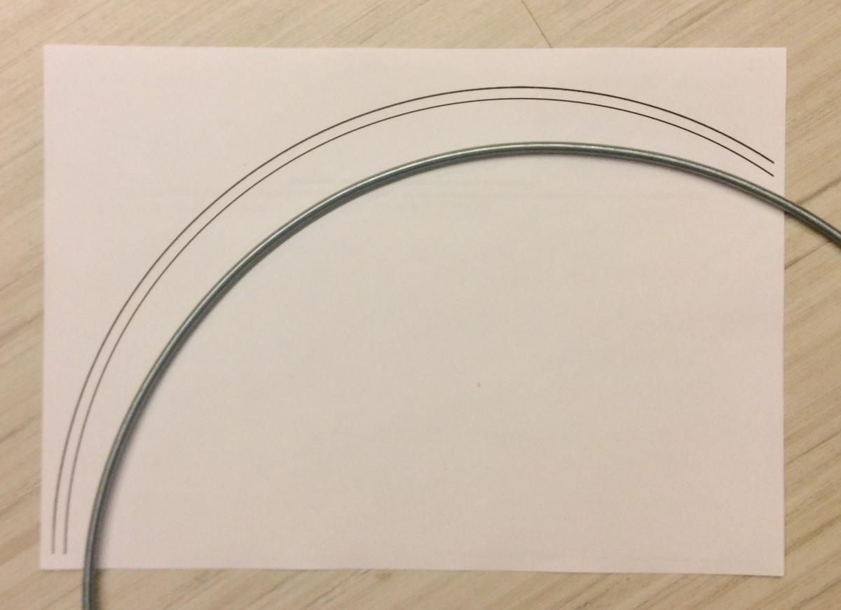
So that tracking would be accurate, a bolt should be curved. Print two concentric circles of the necessary diameter so that their edges would be the size of the bolt. Bend it gradually, putting it on the template for the check. It’s easier to bend the whole bolt at once (it’s 3.28 feet long). You will not be able to curve a short bolt with your hands. Anyway, it was ready in 10 minutes.

Cut the unnecessary with a dremel tool. I left a segment of around 9.84 inches. This will be enough for more than 5 hours of tracking.
Assemble all of them together:
Check the rotation at a written sketch for arduino:
#include
#include
#define HALFSTEP 8
LiquidCrystal lcd(8, 13, 9, 4, 5, 6, 7);
int adc_key_val[5] ={50, 200, 400, 600, 800 };
// Motor pin definitions
#define motorPin1  3     // IN1 on the ULN2003 driver 1
#define motorPin2  4     // IN2 on the ULN2003 driver 1
#define motorPin3  5     // IN3 on the ULN2003 driver 1
#define motorPin4  6     // IN4 on the ULN2003 driver 1
int NUM_KEYS = 5;
int adc_key_in;
int key=-1;
int isRun;
double speeds = 271.6;
int maxspeed = 1245;
AccelStepper stepper1(HALFSTEP, motorPin1, motorPin3, motorPin2, motorPin4);
void setup() {
  lcd.clear();
  lcd.begin(16, 2);
  lcd.setCursor(0,0);
  lcd.print("    Stopped     ");
  lcd.setCursor(0,1);
  lcd.print("Speed ");
  lcd.print(speeds);
  lcd.print("   ");
  isRun = 0;
  stepper1.setMaxSpeed(maxspeed);
  stepper1.setSpeed(speeds);
}
void loop() {
  adc_key_in = analogRead(0);    // read the value from the sensor
  key = get_key(adc_key_in);  // convert into key press
  if (key >= 0)   // if keypress is detected
   {
      if (key == 1) {
         speeds += 0.1;
         delay(50);
      }
      if (key == 2 && speeds > 0) {
         speeds -= 0.1;
         delay(50);
      }
      if (key == 0) {
         speeds += 10;
      }
      if (key == 3) {
         speeds -= 10;
      }
      if (speeds>maxspeed) {
         speeds = maxspeed;
      }
      if (speeds<-maxspeed) {
         speeds = -maxspeed;
      }
      if (key == 4) {
        isRun = 1 - isRun;
        lcd.setCursor(0,0);
        if (isRun == 1) {
          lcd.print("+++ Running +++ ");
        } else {
          lcd.print("    Stopped     ");
        }
        delay(250);
      }
      lcd.setCursor(0, 1);
      lcd.print("Speed ");
      lcd.print(speeds);
      lcd.print("       ");
      stepper1.setSpeed(speeds);
      delay(50);
  }
  if (isRun == 1) {
    stepper1.runSpeed();
  }
}
int get_key(unsigned int input)
{
    int k;
    for (k = 0; k < NUM_KEYS; k++)
    {
      if (input < adc_key_val[k])
            return k;
    }
    if (k >= NUM_KEYS)
      k = -1;  // No valid key pressed
    return k;
}
I used LCD Keypad shield so that it would be comfortable to select rotation speed.

There’re Start and Stop buttons. There’s also an increment/decrement of 25 steps and 0.5 step. The speed is measured in steps per second. Design speed should be 271.6 steps per second. Unfortunately, I am not able to check it, as it rains all the time.
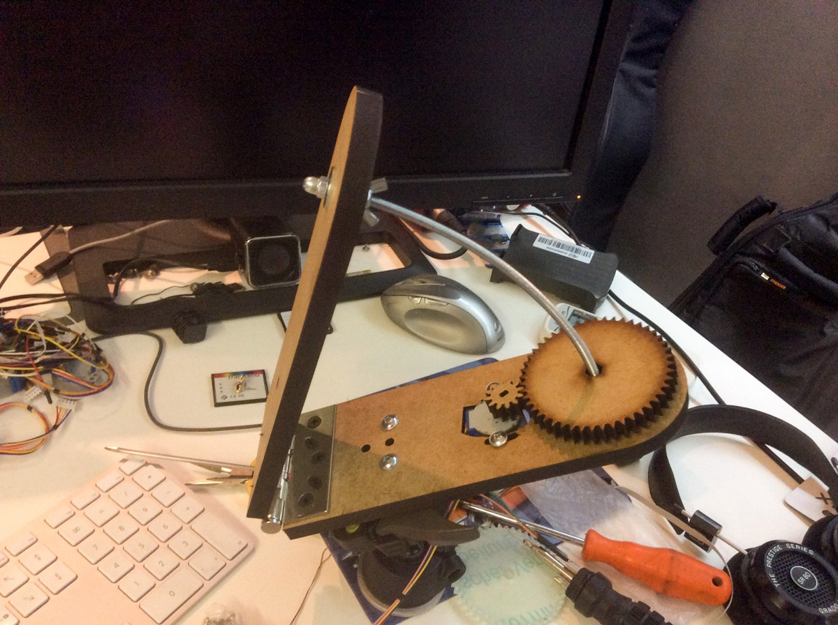
It’s the general view of the construction.

There are two arduinos. Pay no attention to them. I used one of them as the power supply for the motor.
The video of the working process.
I will test it as soon as it stops raining.
Ropes — Fast Strings
Comments
Man Ceamara
hanzzon
Man Ceamara
/* This sketch drives an 28BYJ-48 stepper motor via its ULN2003 driver * initial start speed is 271.6 to drive a screw for tracking stars during astro photography. The value of adc-key-in has been altered to reflect the values delivered by the HobyTronics unit if (adc_key_in < 50) return btnRIGHT; if (adc_key_in < 195) return btnUP; if (adc_key_in < 380) return btnDOWN; if (adc_key_in < 555) return btnLEFT; if (adc_key_in < 790) return btnSELECT; */
#include #include #define HALFSTEP 8 LiquidCrystal lcd(8, 9, 4, 5, 6, 7); int adc_key_val[5] ={50, 195, 380, 555, 790 };
/*Motor pin definitions when using HobbyTronics Keypad shield have been changed to 15 16 17 18. */ #define motorPin1 15 // IN1 on the ULN2003 driver 1 #define motorPin2 16 // IN2 on the ULN2003 driver 1 #define motorPin3 17 // IN3 on the ULN2003 driver 1 #define motorPin4 18 // IN4 on the ULN2003 driver 1
/* original code using the authors keypad, the pinouts have to be changed when using the hobby tronics keypad, this is the original outputs allocated #define motorPin1 3 // IN1 on the ULN2003 driver 1 #define motorPin2 4 // IN2 on the ULN2003 driver 1 #define motorPin3 5 // IN3 on the ULN2003 driver 1 #define motorPin4 6 // IN4 on the ULN2003 driver 1 */
int NUM_KEYS = 5; int adc_key_in; int key=-1; int isRun; double speeds = 271.6; int maxspeed = 1245;
AccelStepper stepper1(HALFSTEP, motorPin1, motorPin3, motorPin2, motorPin4);
void setup() { // void means dont expect any return from this command lcd.clear(); // clear the lcd lcd.begin(16, 2); // set up the LCD’s number of columns and rows: lcd.setCursor(0,0); lcd.print(” Stopped “); // display stopped on the LCD lcd.setCursor(0,1); lcd.print(«Speed „); // display the value of speed lcd.print(speeds); // display the value of speeds lcd.print(“ „); isRun = 0;
stepper1.setMaxSpeed(maxspeed); //1245 stepper1.setSpeed(speeds); //271.6 }
void loop() { adc_key_in = analogRead(0); // read the value from the sensor key = get_key(adc_key_in); // convert into key press if (key >= 0) // if keypress is detected { if (key == 1) { speeds += 0.1; delay(50); } if (key == 2 && speeds > 0) { speeds -= 0.1; delay(50); } if (key == 0) { speeds += 10; } if (key == 3) { speeds -= 10; } if (speeds>maxspeed) { speeds = maxspeed; } if (speeds<-maxspeed) { speeds = -maxspeed; } if (key == 4) { isRun = 1 — isRun; lcd.setCursor(0,0); if (isRun == 1) { lcd.print(“+++ Running +++ „); } else { lcd.print(“ Stopped „); } delay(250); } lcd.setCursor(0, 1); lcd.print(“Speed „); lcd.print(speeds); lcd.print(“ „); stepper1.setSpeed(speeds); delay(50); } if (isRun == 1) { stepper1.runSpeed(); } }
int get_key(unsigned int input) { int k; for (k = 0; k < NUM_KEYS; k++) { if (input < adc_key_val[k]) return k; } if (k >= NUM_KEYS) k = -1; // No valid key pressed return k; }
Kukuruku Hub
Paul
Fried E. Mann
Man Ceamara
#define HALFSTEP 8 LiquidCrystal lcd(8, 13, 9, 4, 5, 6, 7); int adc_key_val[5] ={50, 200, 400, 600, 800 };
// Motor pin definitions #define motorPin1 3 // IN1 on the ULN2003 driver 1 #define motorPin2 4 // IN2 on the ULN2003 driver 1 #define motorPin3 5 // IN3 on the ULN2003 driver 1 #define motorPin4 6 // IN4 on the ULN2003 driver 1
int NUM_KEYS = 5; int adc_key_in; int key=-1; int isRun; double speeds = 271.6; int maxspeed = 1245;
AccelStepper stepper1(HALFSTEP, motorPin1, motorPin3, motorPin2, motorPin4);
void setup() { lcd.clear(); lcd.begin(16, 2); lcd.setCursor(0,0); lcd.print(” Stopped “); lcd.setCursor(0,1); lcd.print(«Speed „); lcd.print(speeds); lcd.print(“ „); isRun = 0;
stepper1.setMaxSpeed(maxspeed); stepper1.setSpeed(speeds); }
void loop() { adc_key_in = analogRead(0); // read the value from the sensor key = get_key(adc_key_in); // convert into key press if (key >= 0) // if keypress is detected { if (key == 1) { speeds += 0.1; delay(50); } if (key == 2 && speeds > 0) { speeds -= 0.1; delay(50); } if (key == 0) { speeds += 10; } if (key == 3) { speeds -= 10; } if (speeds>maxspeed) { speeds = maxspeed; } if (speeds<-maxspeed) { speeds = -maxspeed; } if (key == 4) { isRun = 1 — isRun; lcd.setCursor(0,0); if (isRun == 1) { lcd.print(“+++ Running +++ „); } else { lcd.print(“ Stopped „); } delay(250); } lcd.setCursor(0, 1); lcd.print(“Speed „); lcd.print(speeds); lcd.print(“ „); stepper1.setSpeed(speeds); delay(50); } if (isRun == 1) { stepper1.runSpeed(); } }
int get_key(unsigned int input) { int k; for (k = 0; k < NUM_KEYS; k++) { if (input < adc_key_val[k]) return k; } if (k >= NUM_KEYS) k = -1; // No valid key pressed return k; }
Man Ceamara
hanzzon
Man Ceamara
Man Ceamara
Man Ceamara
hanzzon
In my case I do have access to a laser cutting machine so I’d therefore like the 3D models. I’m simply too lazy to figure out the dimensions by myself :D As it is the motor works fine driven by my Arduino, but it does not make much useful work just sitting there oin my table turning :D
Man Ceamara
Man Ceamara